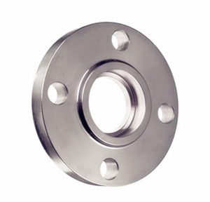
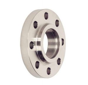
MSS SP-44 Flange Specification
MSS SP-44 refers to the steel pipeline flanges specifications covers pressure-temperature ratings, materials, dimensions, tolerances and testings. Material Grades from F36, F42, F46, F48, F50, F52, F56, F60, F65, F70, F80, which names from yield strength by 36 ksi (F36) to 80 ksi (F80).
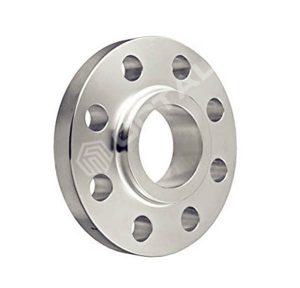
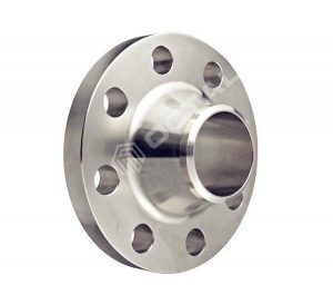
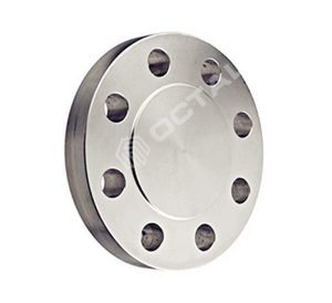
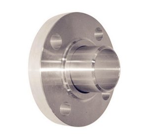
The standard inlcudes all the flange types in forged steel or steel inlcudes Weld Neck Flange, Slip On Flange, Lap Joint Flange and Blind flanges and etc.
Dimensional and tolerance requirements for NPS 10 and smaller flanges in this standard refer to ASME B16.5.
Pressure Temperature Ratings
Flanges understand the standard has follwing pressure ratings: Class 150, 300, 400, 600 or 900.
Sizes
NPS and DN as follows:
NPS | 12 | 14 | 16 | 18 | 20 | 22 | 24 | 26 | 28 | 30 | 32 | 34 | 36 |
DN | 300 | 350 | 400 | 450 | 500 | 550 | 600 | 650 | 700 | 750 | 800 | 850 | 900 |
NPS | 38 | 40 | 42 | 44 | 46 | 48 | 50 | 52 | 54 | 56 | 58 | 60 | |
DN | 950 | 1000 | 1050 | 1100 | 1150 | 1200 | 1250 | 1300 | 1350 | 1400 | 1450 | 1500 | |
Materials of MSS SP-44
All materials used for making MSS SP-44 flanges shall be "killed" steel. It shall be suitable for field welding to other flanges, fittings, or pipe manufactured according to ASTM A105, A53, A106, A350, A381, A516, A537, A694, A707 and API 5L.
It defines maximum carbon content of 0.30%, and CE shall not exceed 0.48%, based on ladle analysis, without prior approval of the purchaser. If the CE exceeds 0.45%, the flange shal be marked with actual CE result. All test methods shall be as specified in ASTM A370.
Chemical Composition
Table 1
Element | Limits (%) | |
|---|---|---|
Min. | Max. | |
C | - | 0.30 |
Mn | 0.60 | 1.60 |
P | - | 0.025 |
S | - | 0.025 |
Si | 0.15 | 0.35 |
Cu | - | 0.40 |
Ni | - | 0.40 |
Cr | - | 0.30 |
Mo | - | 0.12 |
V | - | 0.11 |
Nb | - | 0.05 |
B | - | 0.001 |
Cu+Ni+Cr+Mo | - | 1.00 |
Tensile Requirements
SI (Metric) and U.S. Customary
Table 2.
Grade | Yield Point (Min.) | Tensile Strength (Min.) | Elongation 50mm (2 in.) (Min. %) | |||
|---|---|---|---|---|---|---|
Mpa | ksi | Mpa | ksi | |||
F36 | 248 | 36 | 414 | 60 | 20 | |
F42 | 290 | 42 | 414 | 60 | 20 | |
F46 | 317 | 46 | 414 | 60 | 20 | |
F48 | 331 | 48 | 427 | 62 | 20 | |
F50 | 345 | 50 | 441 | 64 | 20 | |
F52 | 359 | 52 | 455 | 66 | 20 | |
F56 | 386 | 56 | 469 | 68 | 20 | |
F60 | 414 | 60 | 517 | 75 | 20 | |
F65 | 448 | 65 | 531 | 77 | 18 | |
F70 | 483 | 70 | 552 | 80 | 18 | |
F80 | 550 | 80 | 620 | 90 | 16 | |
Impact Test
Impact testing is not required for Grade F42 and lower.
From each steel sheet, one set (three specimens) shall be tested at a maximum temperature of -45℃ (-50℉) and show 27J (20ft-lb) minimum average, 20J (15 ft-lb) individual minium.
Hardness
Hardness shall be HBW 235 as maximum.
Bolting
Boltings listed in Table 3 shall be used in flanged joints covered by MSS SP-44. Bolting produced from other materials may be used if permitted by the applicable code or governmental regulation.
Heat Treatment
MSS SP-42 F42 and higher grades shall be normalized, normalized and tempered, quenched and tempered, or precipitation treated and aged. Class 400 and higher classes of Grade F36 flanges shall be anneald, normalized, normalized and tempered, or quenched and tempered as defined in ASTM A961; But the minimum tempering temperature shall be 540℃ (1000℉).
MSS SP-44 Flange Design Spec
Tolerances
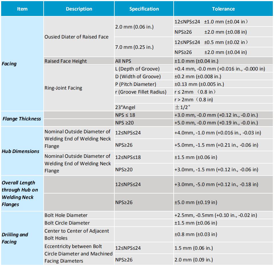
Drilling template
The flange drilling template is determined as follows:
The Class 150 flange drilling template is identical to the Class 125 in ASME B16.5 and ASME B16.1.
The drilled template for class 300 flanges smaller than or equal to NPS24 is the same as that for class 250 flanges in ASME B16.5 and ASME B16.1. The drilled templates for class 400, class 600, and class 900 flanges in sizes less than or equal to NPS24 are the same as those for ASME B16.5.
The NPS 26 through NPS 60 Class 150, 300, 400, 600, and 900 flanges are the same as those of series A flanges in ASME standard B16.47.
Flange Ring design
For flanges with nominal pipe diameter less than or equal to NPS24, the outer diameter and flange thickness shall meet the requirements of ASME B16.5. For flanges with nominal pipe diameters of NPS26 through NPS60, the outer diameter and flange thickness shall comply with the requirements of ASME B16.47 for series A flanges
Hub Design
ASME B16.5 and B16.47 weld flange ratings are based on the weld flange neck and have a calculated wall thickness at least equal to the pipe. The pipe has a specified minimum yield strength of 276 MPa (40000 psi) and a maximum bore size.
NPS 60 and Smaller
When the mechanical properties (minimum yield strength) of the various parts are equal to or greater than the line to which it is connected, the flange neck may be the same size as specified in the ASME B16.5 or 16.47A series.
Marking
Flanges shall be marked in accordance with the rules specified in MSS Standard Practice SP-25. In addition, the letter PL should be added before the level symbol. The grade symbol on the weld neck flange marks the material grade of the weld flange neck.
Facing
The accuracy of the pipe flange contact surface should be determined by the visual comparison method using the Ra sample block instead of the stylus plotter and the electronic magnifier.
Raised Face
It provide concentric serrated or helical teeth with an accuracy between 3.2 μm (125 μinch) and 6.3μm (250μinch). The cutting tool used shall have a radius greater than or equal to 1.5mm (0.06 in) and 1.7 to 2.2 grooves per mm (44 to 55 grooves per inch).
Ring Joint
The side surface roughness of gasket groove shall not exceed 1.6μm (63μinch).
Flange Testing
Hydrostatic test of the flange is not required. However, the hydrostatic pressure test of the flange joint may be carried out at a pressure not exceeding 1.5 times the 38 ° C (100 ° F) rating.

